1.1 Dimensional Analysis of Aluminum Profiles
The dimensions and deviations of extruded components are determined by the die, extrusion equipment, and other related process factors. Among these, changes in die dimensions have a significant impact. These changes are caused by factors including die elastic deformation, die temperature rise, die material, die manufacturing precision, and die wear.
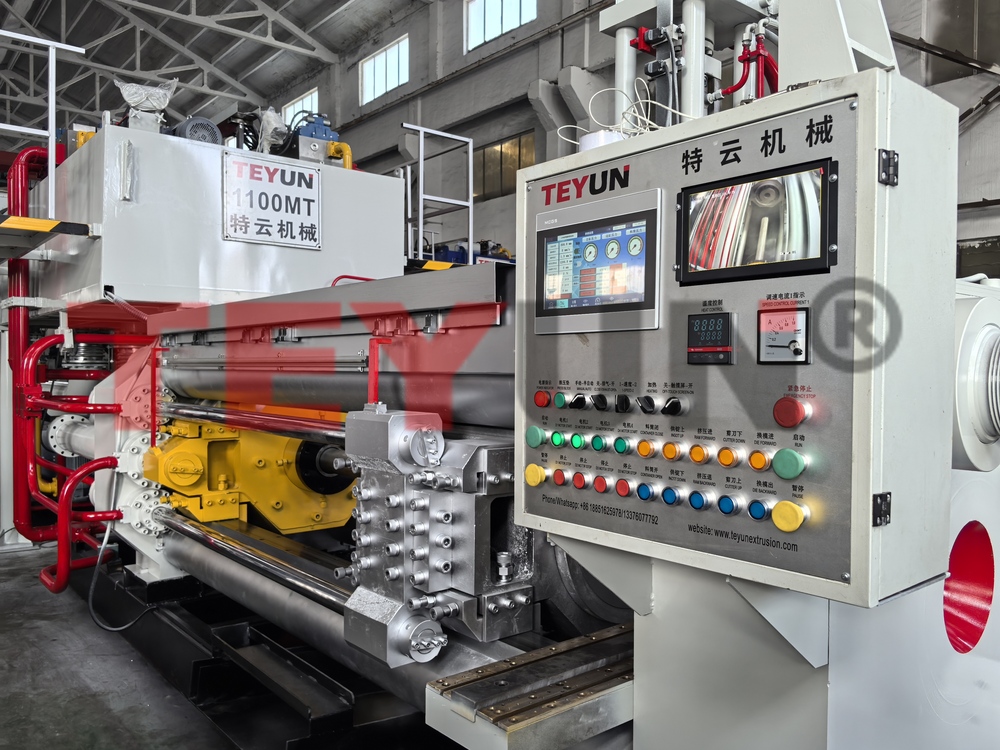
1.1.1 Selection of Aluminum Extrusion Press Tonnage
The extrusion ratio is a numerical value indicating the difficulty of achieving extrusion with the die. Typically, an extrusion ratio between 10 and 150 is suitable. If the extrusion ratio is less than 10, it indicates lower mechanical properties of the product; conversely, if the extrusion ratio is too high, the product is prone to defects such as rough surfaces or angular misalignment. It is generally recommended that solid profiles use an extrusion ratio of approximately 30, and hollow profiles approximately 45.
1.1.2 Determination of Overall Dimensions
The external dimensions of an extrusion die refer to its outer diameter and thickness. The external dimensions of the die are determined by the dimensions, weight, and strength of the profile.
1.2 Reasonable Calculation of Extrusion Die Dimensions
When calculating die orifice dimensions, the chemical composition of the extruded aluminum alloy, product shape, nominal dimensions and their tolerances, extrusion temperature, and the linear expansion coefficient of the die material and extrusion alloy at that temperature, the main considerations are the product cross-section, its geometric characteristics and changes during stretching and straightening, the magnitude of the extrusion force, the elastic deformation of the die, and other factors.
For sections with significant differences in wall thickness, thin-walled sections and sharp edges that are difficult to form should be appropriately enlarged.
For die orifices of flat, wide-walled, and thin-walled profiles, as well as wall profiles with a large width-to-thickness ratio, the truss cross-section dimensions can be designed according to general profile specifications. The web thickness, in addition to considering the factors listed in the formulas, also needs to consider the die's elastic deformation, plastic deformation, and overall bending. The distance between the centers of the extruded cylinder and other factors must also be considered.
Furthermore, the extrusion speed and whether a traction device is equipped will also affect the die orifice diameter.
1.3 Reasonable Adjustment of Metal Flow Rate
Reasonable adjustment aims to ensure that each particle on the product cross-section flows out of the die orifice at the same speed under ideal conditions.
A symmetrical arrangement of multiple orifices should be used whenever possible. Based on the profile shape, differences in wall thickness and specific perimeter among components, and the distance from the extrusion barrel center, design dimension bands of varying lengths.
Generally, the thinner the wall thickness, the larger the perimeter, the more complex the shape, and the farther from the extrusion barrel center, the shorter the dimension band.
When controlling flow rate using a fixed dimension band is still difficult, especially with complex shapes and very thin walls, components far from the center can have their metal flow accelerated by using flow angles or material guide cones.
Conversely, for components with larger wall thickness or close to the extrusion barrel center, blocking angles should be used to assist in blocking, thereby slowing down the flow rate. Furthermore, you can also adjust the metal flow rate by using process balance orifices, process margins, or by using front-cavity dies or flow dividers to change the number, size, shape, and position of the distribution orifices.
1.4 Ensuring Sufficient Die Strength
Due to the extremely harsh working conditions of the die during extrusion, die strength is a crucial factor in die design. Besides rationally arranging the die orifice positions, selecting suitable die materials, and designing a reasonable die structure and shape, accurately calculating the extrusion pressure and checking the allowable strength of each critical area are also essential.
Currently, many formulas exist for calculating extrusion pressure, but the modified Belling formula still holds engineering value. The upper limit solution for extrusion pressure also has good applicability. Calculating extrusion pressure using empirical coefficients is relatively simple.
As for die strength testing, it should be conducted individually based on product type, die structure, etc.
Generally, flat dies only require testing shear strength and bending strength. Tenon and cleaved dies require testing shear strength, bending strength, and compressive strength; tongue and needle dies also require consideration of tensile strength.
A fundamental issue in strength testing is selecting a suitable strength theory formula and a more accurate allowable stress. In recent years, the finite element method has been used to analyze stress and check the strength of complex dies.
1.5 Working Zone Width
Determining the working zone of a split die is much more complex than determining the working zone of a half-die. Not only must the profile wall thickness variation and distance from the center be considered, but also whether the die hole is covered by the split bridge.
Due to the difficulty of metal flow, the die hole below the flow divider must be relatively thin. When determining the working zone, first determine the thinnest wall thickness of the profile below the flow divider, i.e., the part with the greatest metal flow resistance.
The minimum working zone here is set to twice the wall thickness. Thicker walls or metal are easier to access, and the working zone needs to be appropriately thickened based on certain proportional relationships and flow correction values.
1.6 Die Hole Empty Tool Structure
The empty tool of the die hole is a structure supported by a cantilever at the exit end of the die hole working zone. When the profile wall thickness is ≥2.0 mm, an easy-to-machine straight empty tool structure can be used; where there is a cantilever, a T<2 mm or an inclined empty tool can be used.


 Address : NO.7 Huihe Road, Qianzhou Industry park, Huishan District, Wuxi City, China



 IPv6 network supported